Introduction and Objective
VCA compressors are dynamic processors that use voltage controlled amplifiers to limit the dynamic range of an audio, often in a musical context. This allows the compressor to act as a precise volume control, and is often associated with its characteristic sound that is able to grab transient material. Since the gain reduction is handled by a solid state system, the compressor can achieve fast attack and release times. VCA compressors can be transparent in their sound and are used on a large variety of sources and often used for mix bus applications including, but not limited to drums, vocals, bass, and guitar. Most commonly, VCA compressors have a threshold that determines the minimum input voltage that will have gain reduction, a ratio that determines how much gain will be reduced, an attack controlling how fast it takes for gain reduction to occur, and a release that determines how fast the compressor will return to its default state. Some common VCA compressors used in studio environments include the SSL G bus compressor, DBX 160, and API 2500 compressor.
Detailed Circuit Description
Fig. 1: VCA Compressor Schematic in LiveSpice
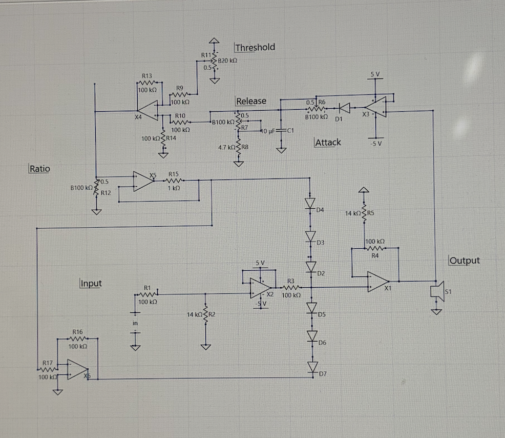
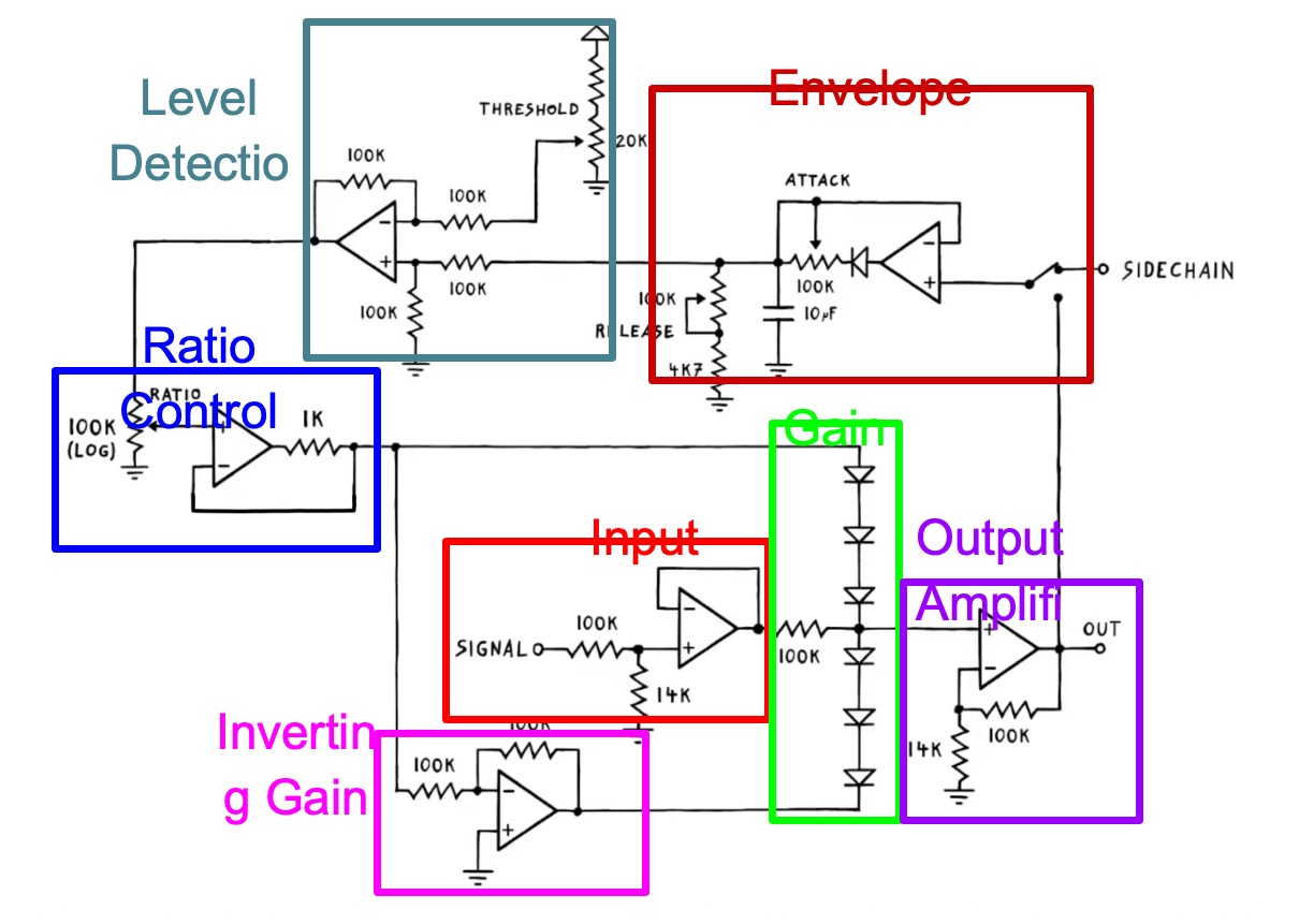
Fig. 2: VCA Compressor Schematic Analysis in Blocks
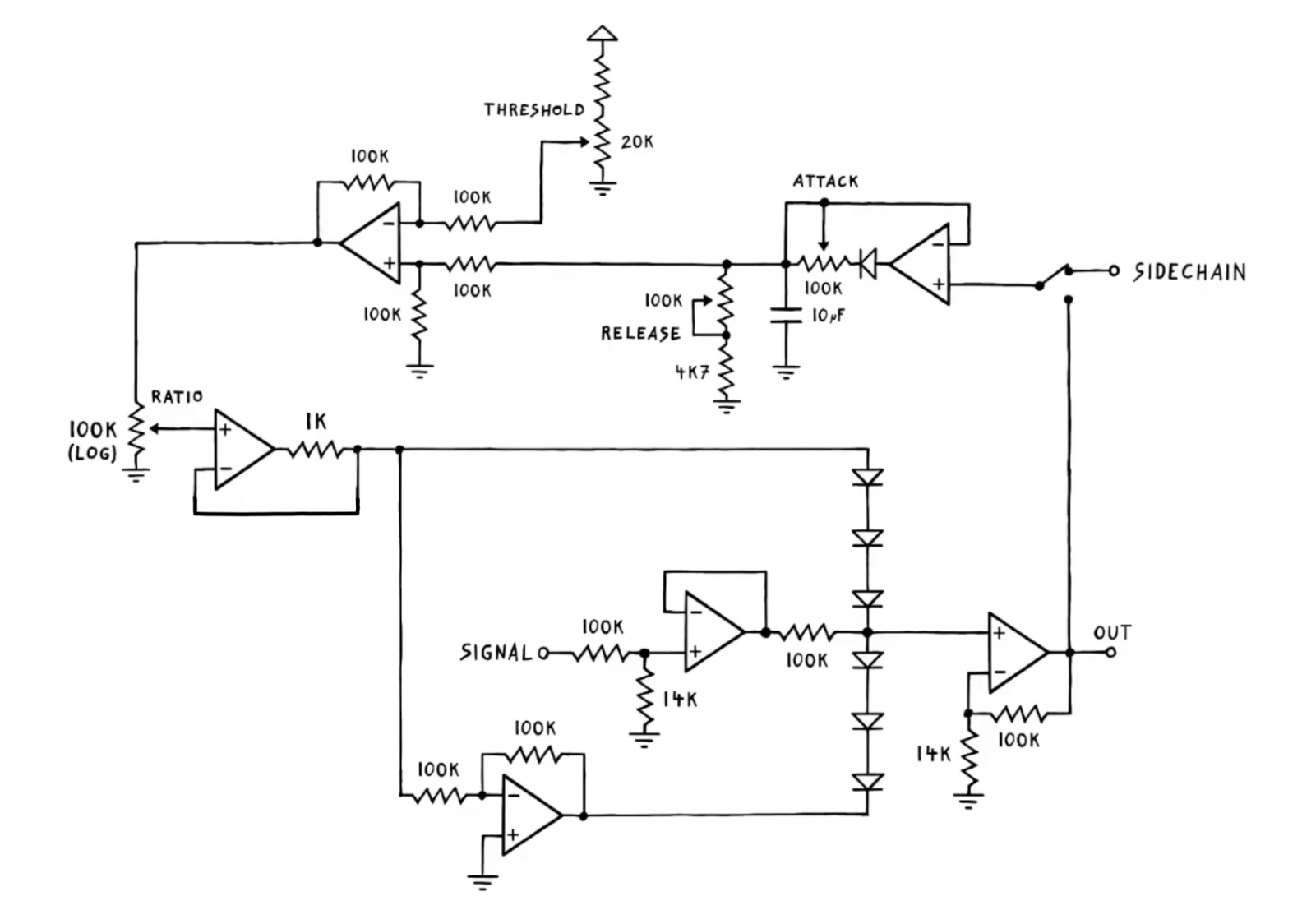
Fig. 2 displays the circuit broken down into individual blocks that each have individual functions and the potentiometers provide the parameters of the processor. The 100kΩ and 14kΩ resistors bias and set the input impedance to ensure that the gain control stage is not overloaded. The gain stage uses a diode ladder to create a voltage dependent resistance so that when voltage increases more, the diodes are more conductive, which attenuates the signal. This attenuation is the gain reduction that creates the compression effect. The ratio control amplifier acts as a gain stage for the gain control block by controlling the voltage entering the gain control section of the circuit. The higher the resistance value, the higher the ratio of compression. The inverting gain stage creates an inverted version of the signal coming out of the ratio control amplifier, helping the diode ladder behave by improving the linear behavior of the gain reduction. The attack time is controlled by the diode in the path of the 100kΩ path, rectifying the signal. The release is controlled by the potentiometer and the resistor going to ground, controlling how fast the gain recovers after the gain control. The output amplifier restores the level and lowers the output impedance.
Fig. 3: Low Ratio Vs High Ratio
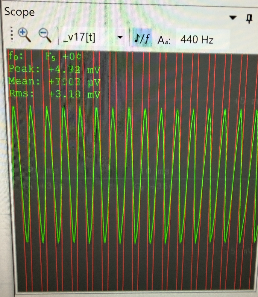
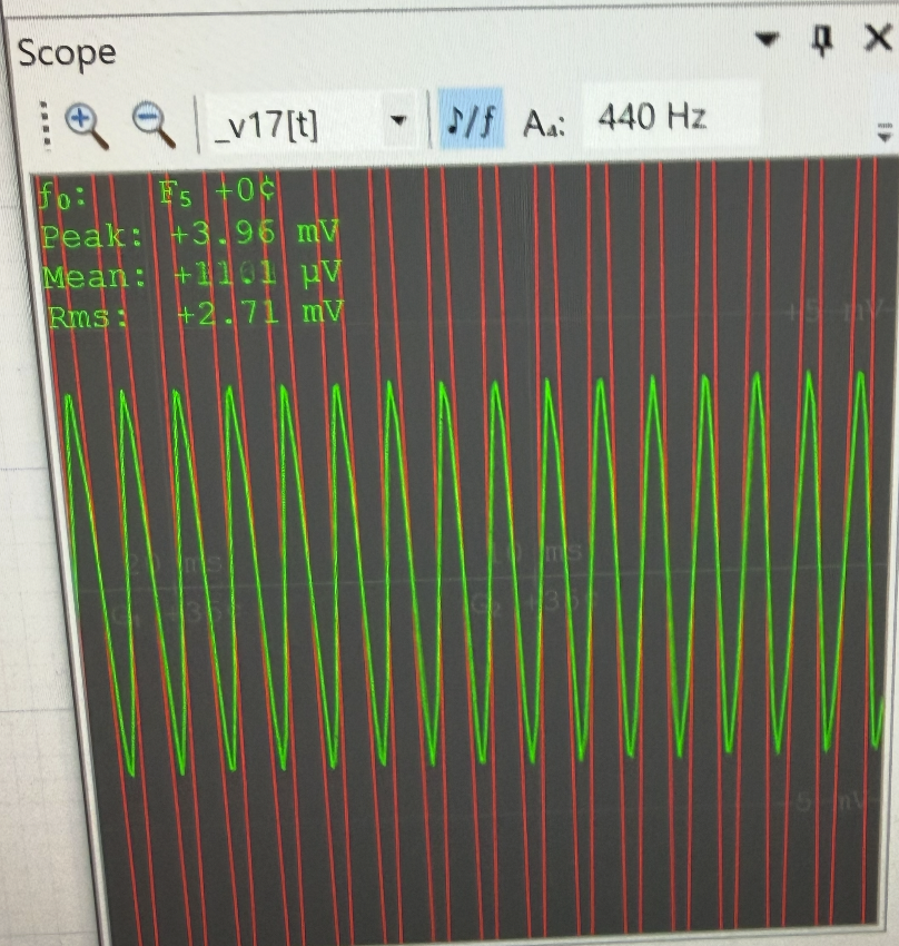
By increasing the ratio knob, the peak voltage goes down due to the increase of gain reduction. Additionally, the RMS is attenuated.
Fig. 4: Low Threshold Vs High Threshold
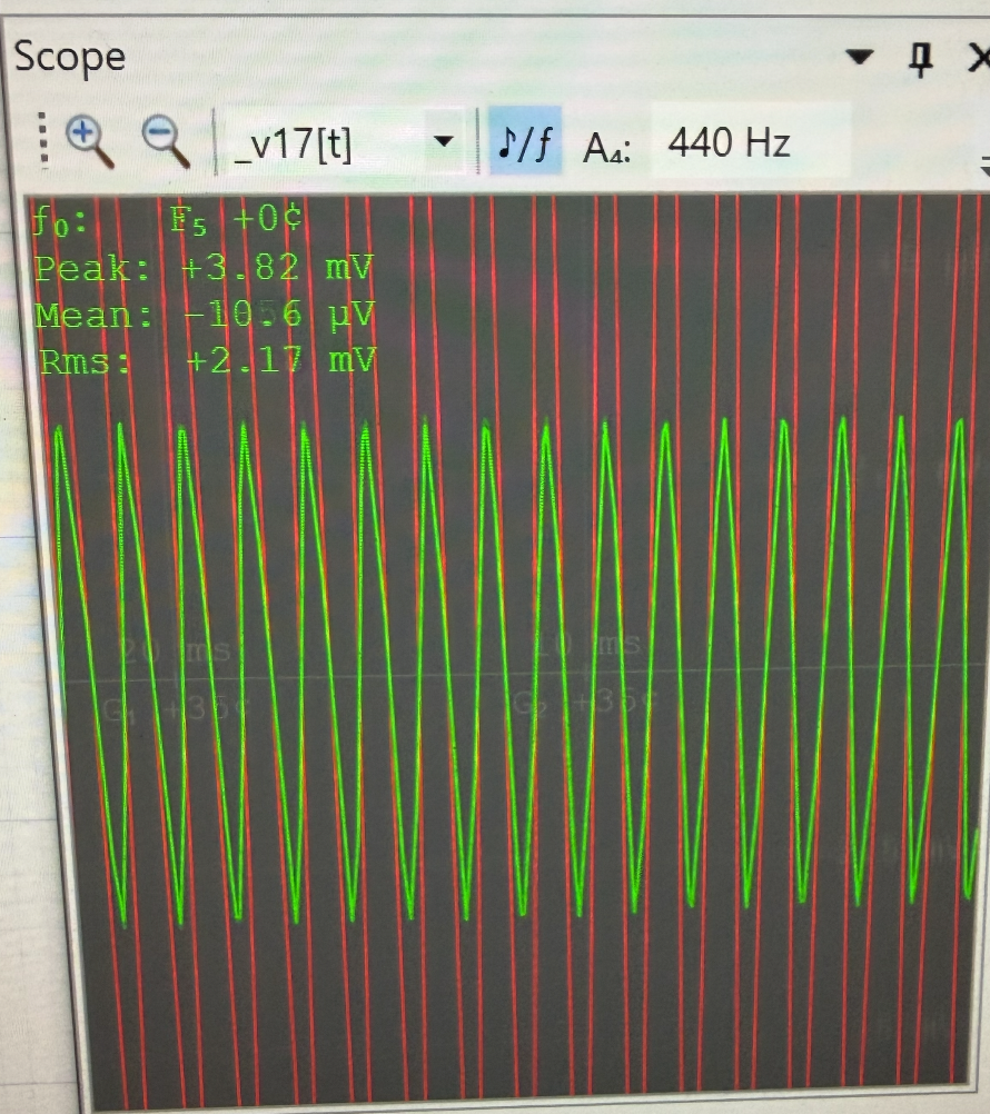
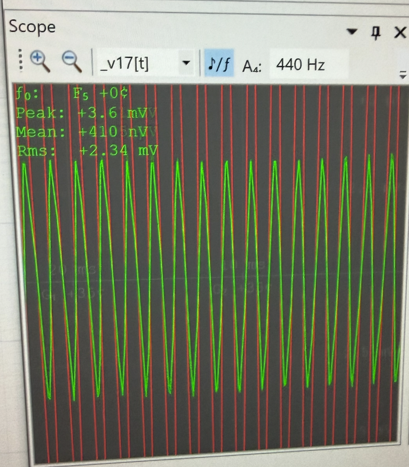
The Threshold controls how much of the waveform enters the gain reduction, and as a result, has a significant impact on the Mean voltage. This is evidence of more of the input signal triggering compression.
Fig. 5: Attack and Release Output Readings
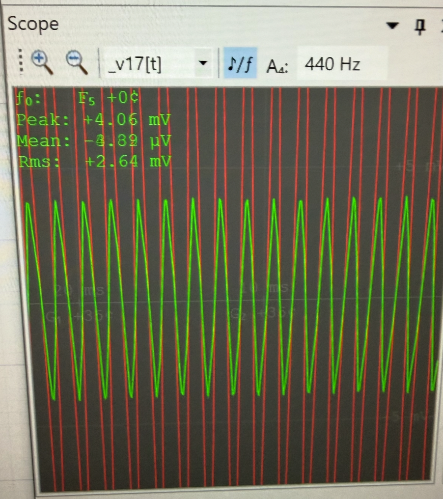
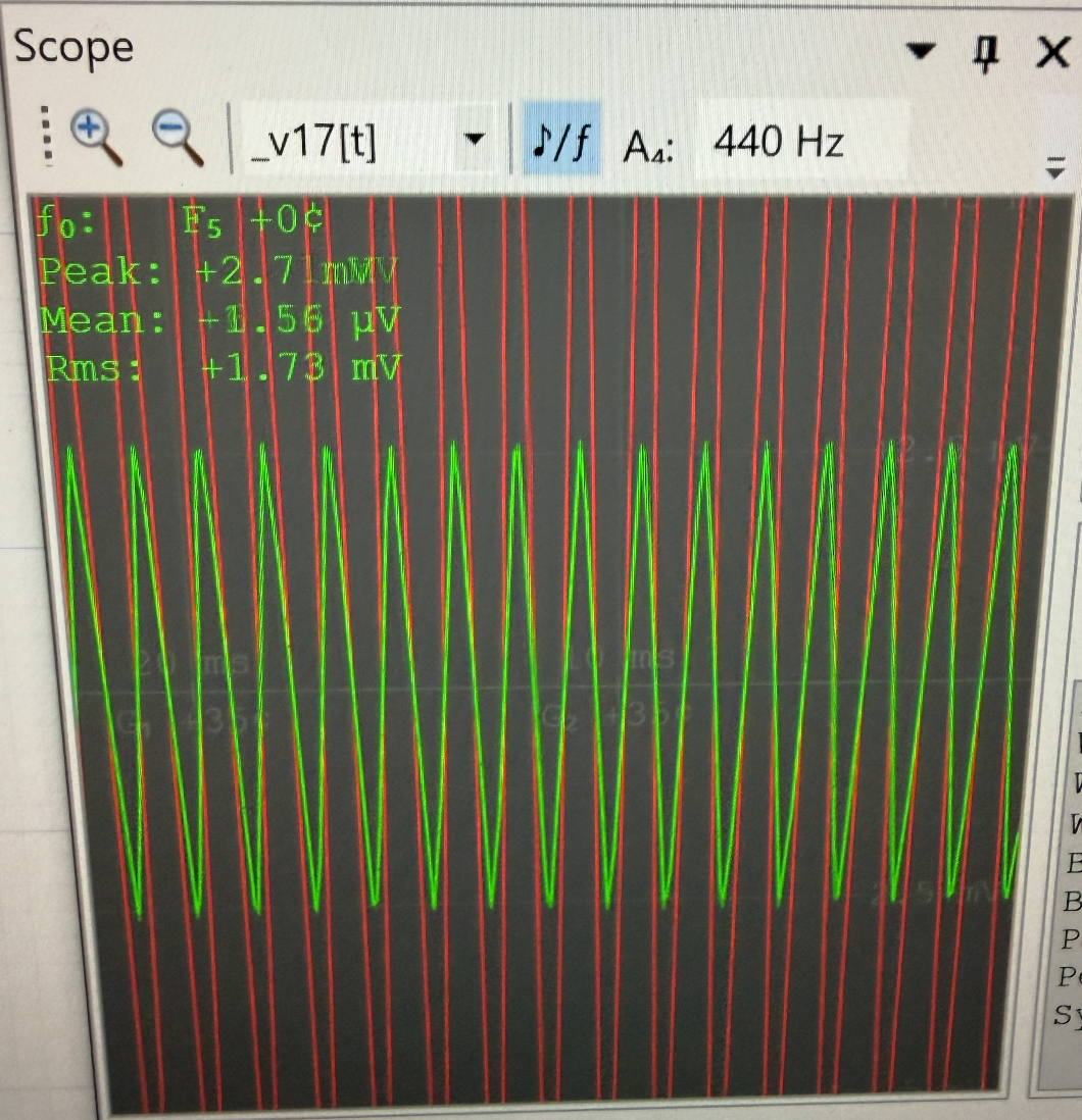
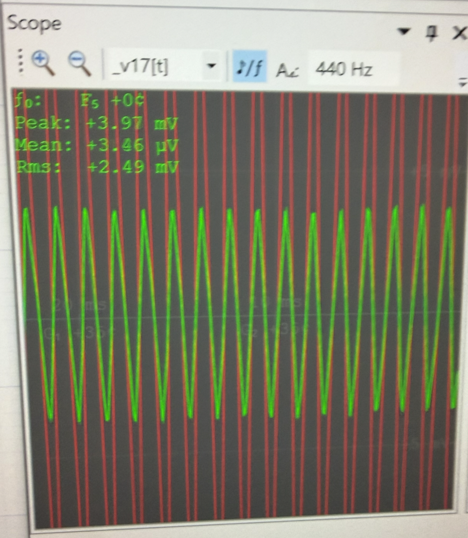
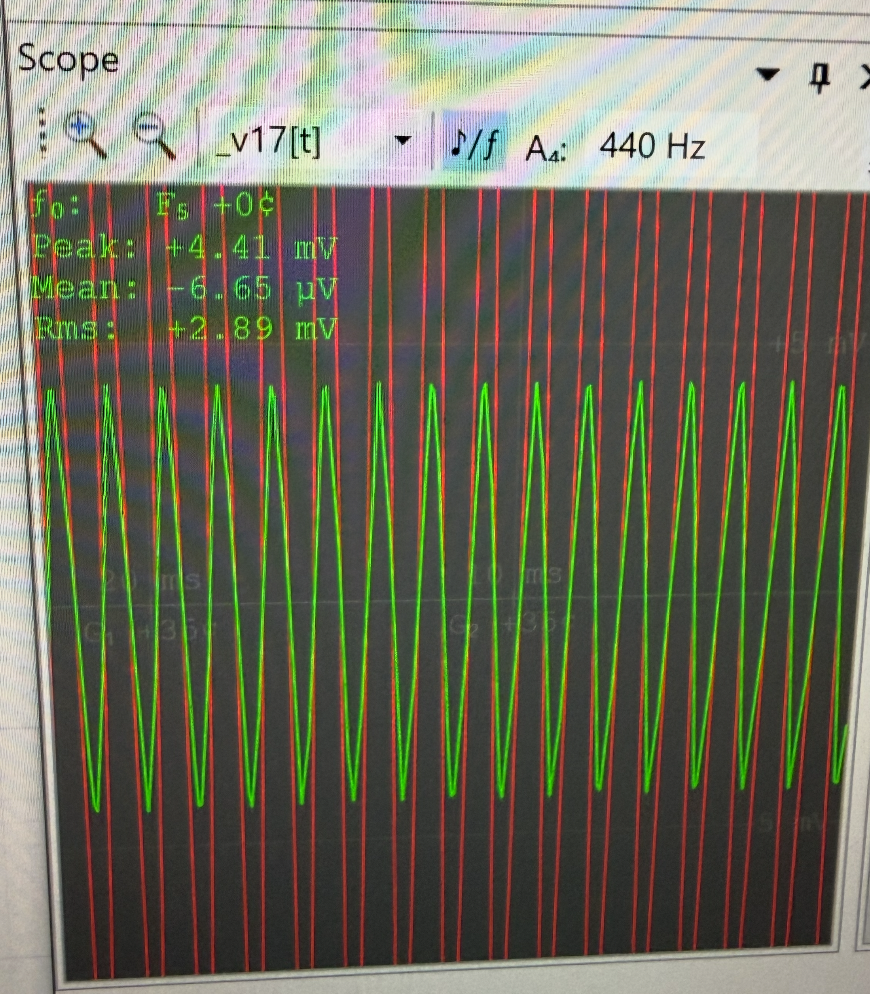
The output voltages for the attack and release controls are not majorly impacted based on the speed. However, they result in very clear audible differences in the signal. With a fast release, the compression effect becomes more pronounced.
Conclusion
The simulation of the VCA compressor circuit in LiveSpice provided crucial insight into how the parameters and circuit blocks contribute to attenuate dynamics. Through analyzing the circuit at a component level, it became clear how each block interacts with the diode ladder and controls the output gain. The envelope following stage allowed the compressor to have variable attack and release times, and the input and output stage were critical to controlling the stability and integrity of the signal. The results from the simulation demonstrated how changing parameter values impact the characteristics of the output signal. In particular, increasing the ratio resulted in greater attenuation, reducing the threshold caused greater attenuation, and the attack and release changed the characteristic of how the compressor sounded. This project reinforced the technical and practical skills of circuit construction and simulation. The ability to gain experience using LiveSpice strengthened skills in circuit creation and debugging.